
Stud Layout: Centre Marks, Edge Lines and the First Offset
A stud centre and a stud edge are different marks. Confuse them and the repeated spacing can look right while a sheet joint lands in the wrong place.
For a regular grid measured from a chosen panel datum, put each stud centre at the required grid position. To mark its near edge instead, subtract half the stud’s actual width. Keep the tape’s zero at the same datum for the whole run.
For example, a centre at 600 mm and a 45 mm-wide stud give a near-edge line at 577.5 mm. A centre at 16 inches and a 1½-inch-wide stud give a near-edge line at 15¼ inches. Neither edge line is the centre.
Here is how to turn those numbers into a readable layout on two wall plates, then keep the same mark list on an iPhone.
Decide what your zero and your marks mean
Start with the wall and panel layout specified for the job. Identify the face or end from which the panel module is set out. Mark it as the datum, with an arrow showing the direction of increasing measurements.
Before drawing repeated lines, decide which of these you are marking:
| Mark | What the measurement locates | How it relates to the stud |
|---|---|---|
| Centre mark | The stud’s centreline | Half the actual width lies on each side |
| Near-edge line | The edge nearer the datum | The stud extends away from the datum |
| Far-edge line | The opposite edge | The stud extends towards the datum |
Marking the far edge is also valid. For the same 600 mm centre, mark 622.5 mm and put the X towards the datum: the stud extends back to 577.5 mm. Keep one edge convention throughout the run.
Use actual width along the plate, measured on the material. Do not substitute a nominal timber size or the depth of the wall.
This example transfers an already chosen grid. It does not choose an acceptable structural spacing, design corners or openings, or specify fastening. Use the job drawings and the applicable framing and panel instructions for those decisions. Panel sizes and required joints or gaps must be included in the original layout; a nominal sheet width is not a reason to change a specified detail.
Worked example: a 600 mm grid with 45 mm studs
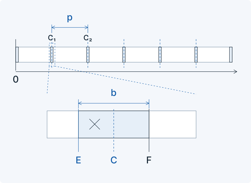
Assume an illustrative straight wall plate 3600 mm long. Its left end is datum zero. An end stud occupies 0–45 mm. The repeated interior stud centres have been specified at 600 mm intervals from that same zero. The panel layout calls for support at the 1200 and 2400 mm module lines.
These are example dimensions, not a recommendation to use 600 mm spacing on every wall.
Let:
- p = 600 mm, the specified centre grid;
- b = 45 mm, the actual stud width along the plate;
- k = 1, 2, 3… for the repeated interior positions.
Then:
Centre Cₖ = k × p
Near edge Eₖ = Cₖ − b/2
Far edge Fₖ = Cₖ + b/2
Here b/2 = 22.5 mm.
| Repeated position | Centre, mm | Near-edge line, mm | Far edge, mm |
|---|---|---|---|
| 1 | 600 | 577.5 | 622.5 |
| 2 | 1200 | 1177.5 | 1222.5 |
| 3 | 1800 | 1777.5 | 1822.5 |
| 4 | 2400 | 2377.5 | 2422.5 |
| 5 | 3000 | 2977.5 | 3022.5 |
Check position 2: (1177.5 + 1222.5) / 2 = 1200 mm. The module line passes through the centre of the stud, leaving 22.5 mm of its width on either side of that theoretical line. Actual panel-edge gaps and fixing distances still follow the specified panel system.
The clear gap between two regular studs is 600 − 45 = 555 mm. It is not 600 mm.
Why the first bay is different
The end stud occupies 0–45 mm, so its centre is at 22.5 mm. The next centre is at 600 mm. Their centre-to-centre distance is therefore 577.5 mm, and their clear gap is 577.5 − 45 = 532.5 mm.
That does not invalidate the interior 600 mm grid. The end stud has a boundary position, while the interior grid is referenced to the panel datum. Moving every interior stud by half a width to make the first bay identical would move the panel-support grid too.
For the same reason, do not automatically put another regular stud centre at the 3600 mm plate end. In this simplified example the far end stud occupies 3555–3600 mm. Its position is set by the end detail. Corners, junctions, openings and additional supports can change that detail; the repeated table is not a complete framing schedule.
Transfer the layout to both plates
- Confirm the grid before marking. Check actual stud width, the panel datum and the required interior centres against the drawings. Mark separately any openings, ends and junctions that interrupt the regular run.
- Align the plates. Put the top and bottom plates together with their corresponding datum ends flush. Label the same end on both. A matching length does not prove that two plates face the same direction.
- Keep one reference. Hold the tape straight and read the near-edge distances from that original zero: 577.5, 1177.5, 1777.5 mm and so on. Do not measure each new mark from the previous pencil line.
- Square the line and identify the material side. In this example, where measurements increase left to right, place an X on the side away from the datum: the stud occupies the 45 mm immediately after the near-edge line. If you reverse the measuring direction, the visual side of the X reverses too.
- Transfer and check. Carry the corresponding marks across both plates. Recheck a panel-module position from the original datum, then verify the end conditions separately before assembly.
A series of equally spaced lines can all be wrong by the same amount. Checking only the distance between neighbours will not reveal a wrong starting offset. Check at least one absolute position as well.
Reading every mark from one datum also avoids propagating the previous mark’s placement error. It does not correct a bad datum, an angled tape, an unreadable pencil line or the wrong side of the line.
The 15¼-inch question at 16-inch centres
For a US-style example with an actual 1½-inch width, half-width is ¾ inch. If the specified interior centres fall at 16-inch multiples from the chosen datum, the near-edge lines are:
| Centre from datum | Near-edge line | Stud occupies |
|---|---|---|
| 16″ | 15¼″ | 15¼–16¾″ |
| 32″ | 31¼″ | 31¼–32¾″ |
| 48″ | 47¼″ | 47¼–48¾″ |
| 64″ | 63¼″ | 63¼–64¾″ |
15¼″ is an edge line; 16″ is the centre. The 48-inch module line passes through the centre of the stud whose near edge is at 47¼ inches.
If a flush end stud occupies 0–1½ inches, its centre is at ¾ inch. The first interior bay consequently differs from the later regular bays. A corner assembly or a different panel starting point may require another offset. Do not apply a ¾-inch deduction to every material or every wall: it comes from half the actual width in this particular setup.
Keep the mark list in Pro²
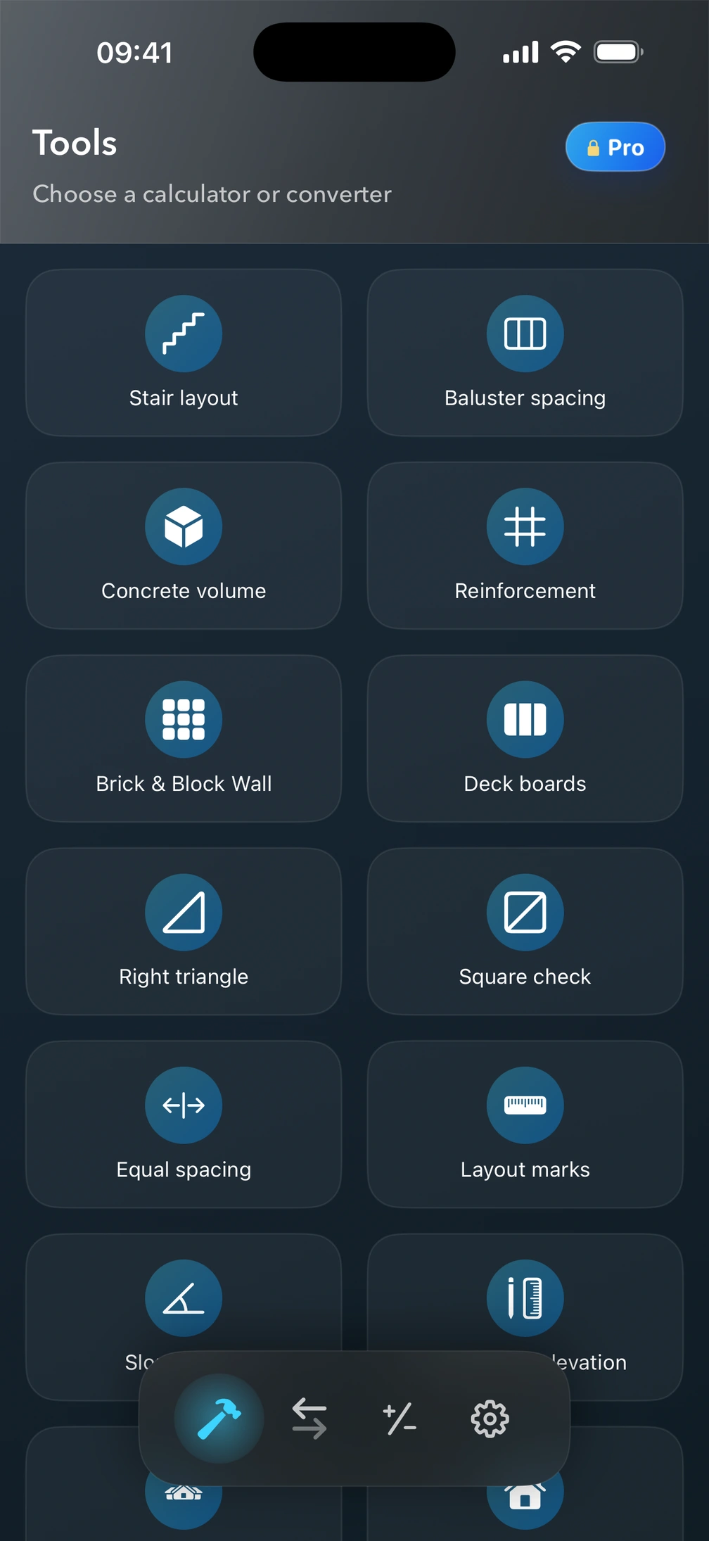
Construction Calculator: Pro² includes a native Layout marks tool. Its inputs are First mark and Mark spacing.
For the metric near-edge list above:
- Open Layout marks on the iPhone and choose metric units.
- Set First mark to 577.5 mm and Mark spacing to 600 mm. Select mm for both fields.
- Calculate and compare the first five results with the table above.
- Use only the positions belonging to your uninterrupted run. In this example those repeated positions end at 2977.5 mm; the far end stud is handled separately.
The tool produces 100 marks, beginning with the value you entered. It does not ask for the wall length, choose the correct offset, deduct half a stud automatically or stop at the end stud. You decide what the numbers represent.
For a centre list, use First mark = 600 mm and Mark spacing = 600 mm instead. For the imperial near-edge example, use 15¼ inches and 16 inches in imperial mode. Keep centre lists and edge lists clearly named so that they cannot be confused on site.
Save the meaning along with the numbers
Give a named calculation a descriptive title, such as North wall · near edges · 577.5 / 600 mm. A name should identify the reference and mark type, not just the room.
Saved Calculations lets you reopen the calculation, change the inputs and update it or save a separate version when your access allows. Auto Resume restores the calculator’s working state and last successful result; use a named save when you need to keep a particular layout deliberately.
The current free allowance is three calculations per local day across the counted tools and one shared named-save slot. Applicable paid access removes those limits for covered tools. PNG/PDF export for supported tools requires applicable paid coverage. Layout Marks exports its mark table; it does not turn the first five rows into a complete wall drawing or automatically remove unused rows.
Check the app and access overview and the local App Store for current options.
Use a different tool for a different spacing question
A fixed stud grid and equal spacing between two endpoints are different jobs. If the drawing specifies a 600 mm module, do not slightly alter every interval merely to reach an end neatly. Deal with that end according to its detail.
For the fixed-step tool’s units, formula and limits, see the Layout Marks guide. For a genuinely adjustable pattern between two ends, see Equal Spacing.
Before assembly, make three checks: same datum, correct mark type, correct side of the line. The list on the phone and the marks on the plates should describe exactly the same thing.
Sources and scope
The calculations and tables here are original worked examples, checked arithmetically; they are not measurements from a completed customer job. The linked ProTradeCraft and Fine Homebuilding guides provide practical framing-layout context. Use the APA technical library and the instructions for the actual panels and assembly for system-specific decisions.