
Tiling set-out: a tile or a grout joint on the centre line?
Marking the middle is only the first decision. The same centreline can pass through a tile or through a joint, and the resulting edge pieces can be very different. Check both phases before fixing the setting-out line.
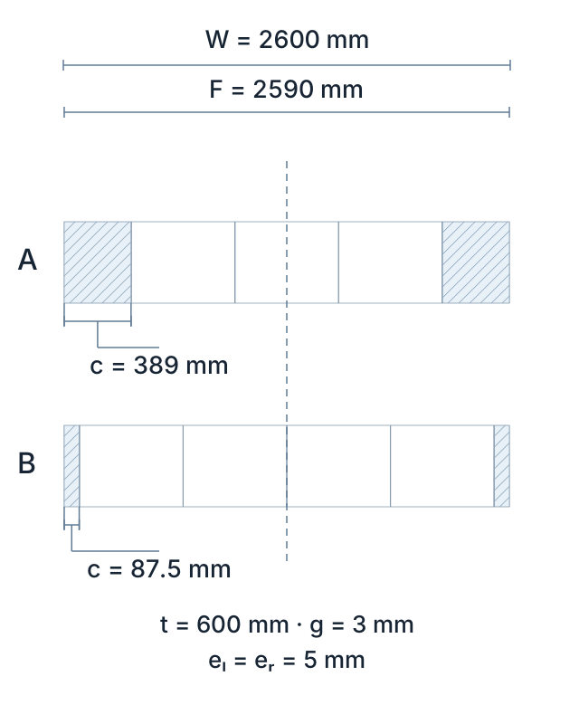
For a 2600 mm span, a measured 600 mm tile face, 3 mm grout joints and assumed 5 mm perimeter gaps at each end, the usable field is 2590 mm. Tile-centreed gives 5 positions and 389 mm edge pieces; joint-centreed gives 6 positions and 87.5 mm edges. The wider cuts are preferable in this example. The gaps are teaching assumptions, not a universal installation specification. This is a worked guide, not an interactive planner.
Measure the faces, joints and usable field
Measure between the finished boundaries that will control the tile field. Check several tiles from the actual batch: the size printed on the carton may be nominal. Enter the face dimension that repeats at the joint, not a decorative bevel's wider visible opening. Choose the ordinary grout width and perimeter movement allowance from the project and product instructions; this geometry does not specify them. For a UK wall or floor tiling job, check the delivered batch and the specified tiling system. A merchant’s nominal format is not a substitute for checking the working size.
- W
- total span between the selected boundaries.
- eₗ, eᵣ
- separate perimeter allowances at the near and far ends.
- F
- usable tile field after those allowances.
- t
- actual tile face dimension along this axis.
- g
- constant ordinary grout-joint width between adjacent tile faces.
- p
- one repeated tile-plus-joint module.
- N
- positive tile positions touching the field, including installed cuts.
- c
- width of each equal edge piece in an admissible multi-piece row.
Two phases around one setting-out axis
Use the midpoint of the usable field for equal edge cuts. A puts a tile's centre on that axis; B puts the middle of an ordinary grout joint on it. Changing phase moves the repeating grid by half a module, including grout: 301.5 mm in the metric example. Moving by half the bare tile alone is not the same operation.
- A · tile-centreed
- B · joint-centreed
Count interior joints before dividing the remainder
A row with two edge pieces and full interior tiles has one fewer ordinary joint than tile positions. Subtract the full interiors and those joints, then share the remaining face length between the ends. The equation below applies only after the count and phase are valid.
F = W − eₗ − eᵣ; p = t + g
x₀ = eₗ + F / 2
F = 2c + (N − 2)t + (N − 1)g
c = [F − (N − 2)t − (N − 1)g] / 2
N ≥ 2; 0 < c ≤ t
N must be an integer of the correct parity: odd for a tile on the axis, even for a joint on the axis. Each edge must be positive and no wider than a tile. Confirm that the tile faces and interior joints close the usable field exactly. If a proposed phase ends inside an ordinary grout interval, it is not a valid equal-edge row under these stated perimeter assumptions; do not invent a tiny extra tile or add another end joint.
Handle a one-position field separately: if F is smaller than t, one centreed cut piece spans F; if they are equal, it is one full tile. That is not a pair of edge pieces. For a multi-position row, c = t means the ends are full tiles, not cuts. For example, F = 2409 mm fits 4 full 600 mm tiles and 3 joints of 3 mm. A zero-width c is never a physical piece. Keep exact input precision when deciding counts; round only the displayed measurement.
Same field, different edge cuts
These are the two valid phases for the stated metric inputs. A's 389 mm ends are easier to accommodate than B's 87.5 mm strips here. This is a comparison of this field, not a rule that tile-centreed always wins or that every job must use cuts larger than half a tile.
| Phase | Positions N | Full interiors | Interior joints | Each edge c (mm) |
|---|---|---|---|---|
| A · tile-centreed | 5 | 3 | 4 | 389 |
| B · joint-centreed | 6 | 4 | 5 | 87.5 |
Resolve both axes, then look at the corners
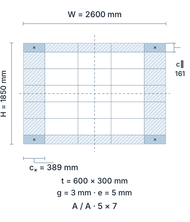
Extend the example to a 2600 × 1850 mm rectangle with measured 600 × 300 mm tiles, the same 3 mm ordinary joints and 5 mm assumed allowances on all sides. The usable field is 2590 × 1840 mm. Choose the phase independently on X and Y; there is no requirement for the same phase on both.
| X / Y phase | Grid positions | X edge (mm) | Y edge (mm) | Full installed | Cut pieces |
|---|---|---|---|---|---|
| A / A | 5 × 7 | 389 | 161 | 15 | 20 |
| A / B | 5 × 8 | 389 | 9.5 | 18 | 22 |
| B / A | 6 × 7 | 87.5 | 161 | 20 | 22 |
| B / B | 6 × 8 | 87.5 | 9.5 | 24 | 24 |
In A/A there are 35 installed positions: 15 full tiles and 20 cut pieces. The cuts comprise 4 corner pieces and 16 other perimeter pieces. Corners are cut in both directions; do not count them twice. These are installed pieces, not an order for 35 new tiles.
Rotating the rectangular tile by 90° swaps its face dimensions. In the rotated A/B example, the grid is 9 × 4, with 233 × 315.5 mm edge dimensions, 14 full tiles and 22 cut pieces. Wider edges on one measure do not establish a universal best orientation: sightlines, pattern direction and the actual cutting plan still matter.
Keep movement allowances separate from grout
An ordinary grout joint belongs between tile faces. A perimeter movement allowance belongs at a restraining boundary and must follow the selected installation system. Do not fill or bridge a required movement joint just to make the arithmetic fit. Internal movement joints divide the field into separately detailed areas and are outside this uninterrupted-grid example. With the same count, increasing g changes the sum of all interior joints and therefore both edge cuts.
Unequal end allowances move the field midpoint. With W = 2600 mm, eₗ = 5 mm and eᵣ = 10 mm, F is 2585 mm and the field axis is 1297.5 mm from the near boundary, not the room midpoint. Tile-centreed then gives equal 386.5 mm faces. If a doorway or feature fixes another axis, equal cuts at both boundaries may be impossible; make a separate site plan rather than applying the symmetric equation unchanged.
Symmetry alone does not make a useful cut
Both tiny and generous edge pieces can be perfectly symmetrical. Compare their actual widths and the visible boundaries before selecting a phase. A field only 80 mm wide within a 600 mm tile still yields a narrow piece; centreing cannot widen the field. If both choices are awkward, discuss another tile format, orientation or setting-out line. The acceptable minimum depends on the product, cutting method, exposure and design; this guide sets no worldwide minimum percentage.
An independent example in fractional inches
Daltile's Quarry Tile sheet lists a 6 × 6 in format and a 3/8 in recommended grout joint. For this separate teaching calculation, assume the checked face is exactly 6 in, the span is 9 ft (108 in), and project allowances are 1/4 in at each end. The usable field is 107 1/2 in. Verify the actual batch and installation specification; these assumed faces and allowances are not a guarantee about every carton or project. The named American quarry-tile example is included to explain fractional inches, not as a UK product or installation specification.
| Phase | Positions | Interior joints | Each edge (in) |
|---|---|---|---|
| A · tile-centreed | 17 | 16 | 5 3/4 |
| B · joint-centreed | 18 | 17 | 2 9/16 |
Installed pieces do not determine the purchase order
Layout positions are locations in the plan. Full tiles are uncut installed elements; cut pieces are the installed fragments. Purchased tiles are the original stock. Two cuts may share a source tile only if the cutting geometry, blade kerf, finish and pattern direction permit it. Offcut reuse, breakage, spares and pack size also change the order. This model does not optimise stock cutting or calculate an exact purchase quantity. An area-plus-allowance estimate is a separate explicitly approximate method, not proof that a cut plan will fit.
Transfer the plan with a dry layout
- Mark the selected field axes and measure to both opposing boundaries; check square and the real wall shape.
- Dry-lay representative rows in both directions with the actual tile spacers and perimeter allowances. Compare the last cuts with the setting-out plan.
- Check door thresholds, sightlines, wall returns and any product pattern direction before fixing the setting-out line.
- Record the approved cuts and a separate cutting/purchase plan. Recheck if tile dimensions, joints, boundaries or orientation change.
Where this model stops
This method covers one rectangular field with straight orthogonal rows, rectangular faces and constant ordinary joints. It does not solve diagonal, herringbone, staggered or decorative multi-format patterns, L-shaped areas, crooked walls, niches, columns, drains, complex doorways or a continuous grid across rooms. It does not design movement accommodation, waterproofing, substrate preparation or compliance. Those cases need their own layout and installation details.
Use the guide; keep the app's capabilities clear
Construction Calculator: Pro² has other geometry and setting-out tools, but a dedicated tile-layout planner is not in the verified public feature set. This guide does not add one to the app and does not promise saved tile projects or tile-plan export. The linked existing tools can help with their stated tasks; they do not replace this tile method or a site-specific plan.
Need a tile planner? Tell us the task and inputs you would use.
Technical sources and assumptions
The method and drawings are our own educational geometry. The sources below support layout practice, terminology, actual-size/joint considerations and movement allowances. CTEF's US workmanship discussion is not presented as a mandatory rule for every country. We read public guidance, not the complete paid ANSI/TCNA standards. The Daltile figures belong to the named product sheet, not all tiles. The chosen dimensions and perimeter allowances remain illustrative.